
How do I install the wires for an iNX/iDX to a TAPCO RRFB?
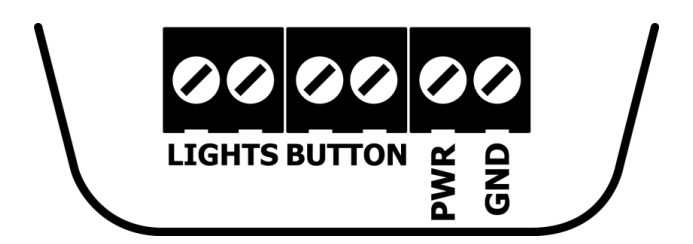
Terminal Block Connections:
PWR (+) & GND (-): The iNX needs 10-24 VDC between PWR (power) and GND (ground) in order to power the button. This voltage must be present at all times for proper operation.
BUTTON (+/-): The iNX accepts 7-32 VDC across button terminals. When the PBS is powered and the physical button is pressed, the voltage will drop to ~0VDC. This is a contact closure connection that signals the RRFB controller to activate the warning lights.
There is no polarity requirement, the terminals accept either orientation.
LIGHTS (+/-): The iNX needs a voltage signal from the RRFB in order to play the warning message. The iNX accepts 7-32 VDC to the LIGHTS terminal. The voice message will not play without the button detecting this voltage. There should be no voltage (0 VDC) when the RRFB warning lights are inactive (not flashing).
There is no polarity requirement, the terminals accept either orientation.
Wire gauge range: 12-28 AWG
For proper long term operation of the button (and consistent voice message play), the LED Flash Behavior setting of the button must be reviewed and changed if needed.
-
Once wires are installed properly, check voltage across the 2 LIGHTS terminals while pushing the button. If the system is activating, you should also get a voltage on the LIGHTS terminals of the button - the voltage should not be present when the system is not active.
-
Log into the button via the Polara FS App and review the Settings from Main Menu > Settings:
- Change the LED Flash Behavior setting based on the reading you get:
- If you get a constant voltage without fluctuations:
- Polara FS App: Settings > LED Flash Behavior = Play Predefined Pattern - Rapid Flash
- If you get a fluctuating voltage:
- Polara FS App: Settings > LED Flash Behavior = Track Ltsln (Track Lights Input)
iNX/iDX To TAPCO Terminal Block with INPUT
|
|

|
iNX/iDX Terminal |
Wire Color |
Terminal Block |
Function |
|
GND |
Black |
0 VDC - |
Common ground |
|
PWR |
Red |
12 VDC+ |
Provides +12 V power to pushbutton |
|
BUTTON (non-polarized) |
Orange |
INPUT |
Button press creates a contact closure triggering the RRFB to start flashing |
|
BUTTON (non-polarized) |
Yellow |
0 VDC- |
Common ground |
|
LIGHTS (non-polarized) |
Blue |
LED2- |
Provides confirmation signal that beacons are flashing to iNX, triggering audio message |
|
LIGHTS (non-polarized) |
Brown |
12 VDC+ |
Provides +12 V to the lights input |
iNX/iDX To TAPCO Terminal Block with N/O
|
|

|
iNX/iDX Terminal |
Wire Color |
Terminal Block |
Function |
|
GND |
Black |
0 VDC - |
Common ground |
|
PWR |
Red |
12 VDC+ |
Provides +12 V power to pushbutton |
|
BUTTON (non-polarized) |
Orange |
COMMON |
Common ground |
|
BUTTON (non-polarized) |
Yellow |
N/O |
Button press creates a contact closure triggering the RRFB to start flashing. |
|
LIGHTS (non-polarized) |
Blue |
LED2- |
Provides confirmation signal that beacons are flashing to iNX, triggering audio message |
|
LIGHTS (non-polarized) |
Brown |
12 VDC+ |
Provides +12 V to the lights input |