EN4/PHCU4W APS System Troubleshooting
Diagnostic LED Indicators
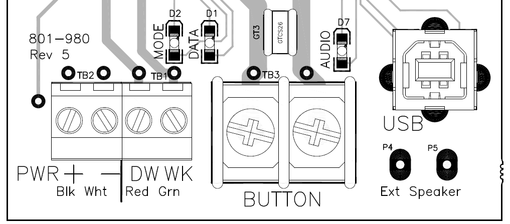
With the small cover at the bottom of the EN APS removed, you will see three small LEDs located in the area above the terminal blocks. When the unit is powered up and is in normal operation the LEDs will blink at various frequencies:
MODE:
- Don't Walk - On steady
- Walk - Rapid flash (10/s)
- Clearance - Slow flash (1/s)
DATA:
- Shorter blink when sending play command from the MP (microcontroller processor) to the AP (audio processor)
AUDIO:
| Button Creates a Constant Call |
|
- Verify interval is being received by button:
- During Don't Walk: Measured voltage between DW (red wire) and PWR- (white wire) should be ~20VDC (Locate Tone should typically be heard during Don't Walk)
- If voltage is incorrect, verify DW input voltage on PHCU4W control module in the ped head (120VAC on DW).
- During Walk: Measured voltage between WK (green wire) and PWR- should be ~20VDC.
- If voltage is incorrect, check WK input voltage on PHCU4W control module in ped head (120VAC on WK).
- During Clearance/Countdown: Measured voltage between DW (red wire) and PWR-, should be ~20VDC for half a second, then 0VDC for half a second (.5s on and .5s off continuously for the full clearance duration)
|

|
- If interval voltage is correct, measure voltage (8-24VAC/VDC) across BUTTON terminals.
- Should measure between 8-24VAC/VDC
- If not within range, then disconnect field wiring from terminals and measure across wires.
- If still not within range, narrow problem to field wiring or PED CALL Input.
- If within range, RMA button.
Note: PED CALL Inputs are referenced to either AC NEUTRAL or LOGIC GND (depending on the cabinet).
|

|
| Button Will Not Place Call |
|
- Verify interval is being received by button:
- During Don't Walk: Measured voltage between DW (red wire) and PWR- (white wire) should be ~20VDC (Locate Tone should typically be heard during Don't Walk)
- If voltage is incorrect, verify DW input voltage on PHCU4W control module in the ped head (120VAC on DW).
- During Walk: Measured voltage between WK (green wire) and PWR- should be ~20VDC.
- If voltage is incorrect, check WK input voltage on PHCU4W control module in ped head (120VAC on WK).
- During Clearance/Countdown: Measured voltage between DW (red wire) and PWR-, should be ~20VDC for half a second, then 0VDC for half a second (.5s on and .5s off continuously for the full clearance duration)
|
|
- Measure voltage (8-24VAC/VDC) across BUTTON terminals.
- Should measure between 8-24VAC/VDC when button is not pressed.
- When button is pressed the voltage should drop to ~0VAC/VDC. If not, RMA button.
- If voltage does drop to ~0VAC/VDC, check if ped isolators are present. If yes, the voltage may not drop enough for the controller to register a call.
- If the voltage drops to ~0VAC/VDC and no ped isolators are present, manually short the cabinet's PED CALL Input to see if a call is placed. If not, the controller is not configured properly.
|
|
|
|
| Will Not Power On |
|
- Measure voltage (~20VDC) between PWR+ & PWR- on 4-port terminal block
- If no voltage, check for 12-14 gauge wire and wiring between PHCU4W and EN4
- Check input voltage on PHCU4W. There should be 120VAC on either DW on WK In
|
|
- Verify interval is being received by button:
- During Don't Walk: Measured voltage between DW (red wire) and PWR- (white wire) should be ~20VDC (Locate Tone should typically be heard during Don't Walk)
- If voltage is incorrect, verify DW input voltage on PHCU4W control module in the ped head (120VAC on DW).
- During Walk: Measured voltage between WK (green wire) and PWR- should be ~20VDC.
- If voltage is incorrect, check WK input voltage on PHCU4W control module in ped head (120VAC on WK).
- During Clearance/Countdown: Measured voltage between DW (red wire) and PWR-, should be ~20VDC for half a second, then 0VDC for half a second (.5s on and .5s off continuously for the full clearance duration)
|
|
| Will not play audio or distorted audio (Custom Messages only) |
- Ensure Walk Mode Sound is set to "Custom Walk 1" and Information Message is set to "Custom (With Pulse)" using either the EZ APS Toolbox (under Configuration tab) or an ECONFIG
|
- Make sure audio file is a *.wav file. If not, modify the audio file to *.wav format using Audacity software or look in the Polara server audio library for an existing wav audio file.
|
- If audio is still distorted or will not upload, it may be corrupt. Either request a new audio file from Polara/your distributor, or create a new file using an audio recording application such as Audacity
- Settings must be: Mono, 16kHz, 32-bit float
|
| Will not play audio or distorted audio (All sounds) |
| Power cycle the button by disconnecting then reconnecting one of the button power wires |
|
Plug into the USB port and access the button using the EZ APS ToolBox,
Check Audio Programming tab, Restore Defaults.
Unplug USB and check operations of sounds
|
|
Measure resistance across the speaker terminals. If significantly less or greater than 8 Ohms, then:
- RMA the APS for evaluation
- Order a Field Installable Speaker (PN: 850-187)
|